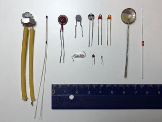
A few different models of NTC: some are color-coded with the R25 value, some are extremely small to minimize thermal mass and some others are designed to be easily mounted on a heat sink. (click to enlarge).
Negative temperature coefficient resistors (NTCs) or thermistors are widely used as temperature sensors and as inrush current limiters in a variety of applications. Their main characteristic is that their resistance varies as a function of temperature: the hotter, the less resistance.
As temperature sensors, they have many advantages: they are cheap, they are available in many different shapes and sizes and in a wide nominal resistance values (roughly from 1 Ω to 10 MΩ). More importantly, they present wide variations of their resistance as a function of temperature, allowing simple thermometer and thermostat circuits without the need of complex amplifiers.

A few different models of NTC: some are color-coded with the
R25 value, some are extremely small to minimize thermal mass and
some others are designed to be easily mounted on a heat sink.
(click to enlarge).
On the downside, their characteristics are non-linear making direct reading of the temperature a difficult task with analog electronics, but this problem is easy to solve with a modern microcontroller. Their temperature range is somehow limited to "common" temperatures and depends on the exact model, but as a rule of thumb, they normally operate between −50 to +150 °C. High precision is usually not achieved with NTCs, even if some exceptions exist.
The resistivity of the vast majority of electrical conductors (metals) normally increases with temperature, i.e. they have a positive temperature coefficient (PTC). But this resistivity change is pretty small: for example, the resistivity temperature coefficient of copper is only 0.0039 K-1 at 20 °C. Of course, this phenomenon can be (and is) used to measure the temperature, but the small signals involved add complexity to the circuit.
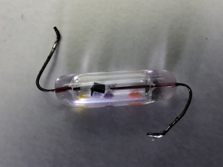
A close-up of a glass type NTC where the actual "chip" can
be seen. (click to enlarge).
Semiconductors, on the other hand, are an exception: their resistivity goes down as the temperature increases and the change is much higher. For example, the temperature coefficient of un-doped silicon is −0.075 K-1 at 20 °C. Even if silicon is used as temperature sensor, NTCs are usually constructed with metal oxides, shaped and sintered together, and have even higher temperature coefficients. Common materials are oxides of iron, nickel, cobalt, manganese and copper. This allows simple and very sensitive temperature sensors providing very large signals.
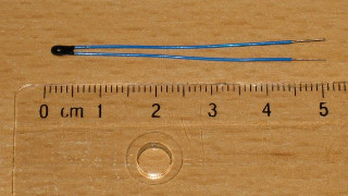
Picture of a tiny NTC used here as example for the calculations.
R25 = 6.8 kΩ and
β = 4200 K. (click to enlarge).
The downside is that their resistance is not a linear function of the temperature as one can see in the two plots below (which refers to an NTC specified R25 = 6.8 kΩ and β = 4200 K). Even by restricting the temperature range (say from 0 to 50 °C), the function can hardly be approximated by a line. As explained before, in an NTC the resistance decreases as the temperature increases.

.png)
Variation of the resistance as a function of temperature, both axes
are linear.
The image on the right shows a zoom of the range from 0 to
50 °C.
The resistance actually varies as the exponential of the inverse of the absolute temperature. As expected, by plotting the resistance with a logarithmic scale and the inverse of the absolute temperature (1/T) the function become a straight line.
-T.png)
-T-1.png)
Variation of the resistance as a function of temperature, with
logarithmic resistance axis.
The image on the left has a normal temperature axis, while the one on the
right shows the inverse of the absolute temperature (1/T) instead: here the
function becomes a straight line.
The temperature characteristics of NTCs are specified with two major parameters: the nominal resistance noted R25, which is their resistance at the standard temperature of 25 °C (T25 = 25 °C = 298.15 K) and their constant β (beta) which somehow represents the "temperature coefficient" or "sensitivity". Common NTCs have β values in the 3'000 to 5'000 K range.
With these parameters the resistance (or the temperature) can be calculated as follows:
![R(T) = R_25 * e ^ ( beta * ( ( 1/T ) - ( 1 / T_25 ) ) ) [Ohms]](R(T).png)
![T(R) = 1 / ( ( ln( R / R_25 ) / beta ) + ( 1 / T_25 ) ) [K]](T(R).png)

These equations use the absolute temperature in Kelvin (K), if you use a different scale, you should convert it first.
This is a "simple" theoretical model and allows a precision of about ±1 % after a good calibration. If higher a precision is required, it can be obtained by limiting the temperature range, by using a precision (and expensive) NTC and a more complex mathematical model. However, even with the best techniques, don't expect anything much better than ±0.1 % from an NTC.
The following calculator uses the above equations to calculate the resistance or the temperature of a known NTC. Just enter the known temperature or resistance and press the corresponding "calculate" button. In order to work, you need to provide the two characteristic parameters of the NTC: R25 and β.
If the parameters of the NTC are not known, they can be determined with just two sinple measurements (see below).
With modern microcontrollers, it's easy to program these equations and get direct readings in °C (or the temperature unit of your choice) without the need of complex analog linearizing circuits.
There are however a few downsides that should be mentioned: first the working temperature range is limited to about −50 to +150 °C depending on the particular model of NTC. Then, because of the logarithmic change of resistance, the wider the temperature range accepted by the circuit, the lower the precision.
Furthermore, NTCs are usually not factory calibrated: the actual R25 and β vary from one NTC to another and some sort of circuit adjustment or calibration is always required to do absolute and precise temperature readings.
When using an NTC as a temperature sensor, one should also be careful in not running to much current though it, since the current will heat the NTC and introduce a measurement error. For this reason, high value NTCs (10 kΩ or more) are better for thermometers. Try to run the lowest possible current, less than 1 mA, if you can. To determine if the NTC is heating itself in common (low precision) applications, try to blow some air on it and observe if there is any variation in the readings. Of course, you shouldn't blow with your mouth as the air you breathe is normally hotter than the ambient air: just move some air on the NTC with a piece of cardboard. No variation should happen: if the measured temperature decreases by this additional cooling, you may want to reduce the current in your NTC.
Suppose you have an NTC in your hands and you want to know what the main characteristics R25 and β are. Sometimes, the nominal resistance R25 is marked on the component itself, but I've never seen and NTC with β printed on it.
There are many reasons you may want to do this: probably, if you are a homebrewer, you have a junk-box full of parts and you are looking for a suitable NTC. Maybe you are repairing some device and you need information on an NTC but you don't have the service manual. Or, more likely, you're just calibrating a thermometer and you need precise values for R25 and β.
Very often, the exact parameters of an NTC are not known. Fortunately, both R25 and β of any NTC can easily be determined by measuring the resistance at two different temperatures that I'll call T1 and T2. Knowing the corresponding resistances R1 and R2, we can use the following equations:
![beta = (ln(R_1) - ln(R_2)) / ((1/T_1) - (1/T_2)) [K]](beta.png)
![R_25 = R_1 / ( e ^ ( beta * ( ( 1/T_1 ) - ( 1 / T_25 ) ) ) ) [Ohms]](R25.png)
The following calculator will do the math for you: just enter two temperatures, the corresponding measured resistances and hit the "calculate" button. Please remember that the lower temperature corresponds to the higher resistance.
Measuring the resistance of an NTC can be tricky. You need a multimeter and a reference thermometer, i.e. a thermometer you trust. It's important to make sure that they both read the same temperature: so put the NTC under test and the probe of your thermometer very close together. I usually put a drop of thermal paste between the two to improve the thermal conductivity. The same thermal compound used to mount power components on heat sinks works well.
To get accurate values, use two temperatures that are as far apart as you can (or as it makes sense in your application). Manufacturers usually choose 25 and 85 °C or 25 and 100 °C as standard temperatures and specify β25/85 or β25/100, to tell which temperatures have been used, but you can use any temperature you want, the actual value of β should be roughly the same. For one measurement, maybe you can get by with just the ambient temperature you have in your lab. But for the other one at least, you need to be a little creative: try doing the measurement outside, or in the basement. Maybe you can put everything in the fridge. Avoid direct sunlight as it may introduce errors due to the different thermal emissivity and thermal mass of the two sensors. For all measurements, make sure you let enough time to the NTC to stabilize to the new temperature and after being manipulated: wait until the reading is stable and this may take a few minutes. Do not stand too close and don't breathe on the test setup.
We know that a NTC varies its resistance as a function of the temperature, but resistance is not the easiest parameter to measure. What we want to do in many applications is to feed a signal into an analog-to-digital converter (ADC) to treat it numerically and compute the actual temperature. Now, the large majority of ADCs require a voltage at their input.
What we want to avoid is building complicated analog circuits to shape or linearize the signal. We have already seen that the resistance as a function of temperature R(T) of a NTC is a complicated function and requires some math anyway, so it's not worth building a circuit to linearly transform its resistance into a voltage.
The easiest solution (and also the one I prefer) is to install the NTC in a voltage divider as shown in the circuit below. It requires only one additional fixed resistor RF and an extra optional capacitor C. UREF is the reference voltage used by the ADC: sometimes it's supplied by the ADC itself, sometimes by an external voltage regulator and sometimes it can simply be the positive supply rail VDD of the microcontroller or ADC. Here, we assume that there is some circuit supplying a stable reference voltage UREF to both the voltage divider and the ADC.
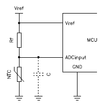
Typical connection of an NTC in a voltage divider to drive the ADC of
a microcontroller.
The optional filter capacitor is a good idea to reduce noise.
I personally like to have one lead of the NTC connected to ground, but it's also possible to "mirror" the circuit and have the NTC connected to UREF. For simplicity, all the considerations in this page, are meant with the NTC towards ground.
It's good practice to add a capacitor to ground in order to filter the noise picked up by the wires connecting the NTC. Temperature variations usually have long time constants (seconds, if not minutes), so a fairly big capacitor can be used. If you're lazy like me, just pick one of several μF and see what happens... otherwise do the math and calculate the RC time constant and make sure it's as large as you can but much smaller than the one of the temperature you're willing to measure.
We already covered the equation that allows calculating the temperature corresponding to a given resistance of your NTC, but all your ADC will tell you is the voltage at its input terminal. To determine this resistance you still need the equation of the voltage divider, which is as follows:
![U_out(T) = U_ref * R(T) / ( R_f + R(T) ) [V]](Uout(T).png)
Or, expressed in the other way around:
![R(T) = R_f * U(T) / ( U_ref - U(T) ) [Ohms]](Rntc(T).png)
It assumes that the input impedance of your ADC is infinite, but this is a quite good assumption as modern ADCs really have a very high input impedance.
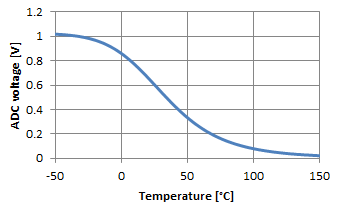
Again, this equation is not linear and further distorts the response curve of your temperature sensor, but if you plot it on a graph (see below), we have quite a good surprise: the curve is now more "symmetric" and straight in the middle range of the temperatures, avoiding too small or too large values as we had when dealing directly with the resistance. If we only look at the 0 to 50 °C range of this example, we see that the response is quite straight: by carefully selecting the fixed resistor RF we can achieve a surprising accurate result by just approximating it with a straight line. In the figure below (right graph) the error is within ±2 % between 0 and 50 °C with your "usual" 6.8 kΩ 4'200 K NTC and an RF of 4.7 kΩ. The dotted line is just a straight line to show how close this approximation can be. If your application can tolerate such approximation and a limited temperature range, you don't need to do any complex math; just take two points and interpolate with a straight line. If not, use the equations of the voltage divider and of the NTC to calculate T.
.png)
Variation of the ADC voltage as a function of the temperature.
Please remark how straight the curve looks in the reduced temperature range
of 0 to 50 °C where the error can be below 2 %.
The dotted line is a straight line.
In any case, selecting RF requires some thinking. Choosing RF equal to R25 is a good starting point: this makes the output of the divider exactly half the reference voltage at 25 °C. The best precision will be around this temperature because the slope of the curve is the steepest and will degrade with higher and lower temperatures where the slope becomes more flat. If you're interested in cold temperatures, choose a larger RF; conversely a smaller RF will shift the precision toward hotter temperatures. The figure below summarizes the effect of RF on the voltage divider response. If you plan to approximate with a straight line, you may have to play around a little with the value of RF to find the best possible match with the thermistor you have and the temperature range you want to achieve.
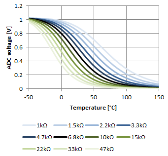
Influence of RF on the voltage as a function of the
temperature with our example NTC.
The middle (black) curve corresponds to
RF = R25 = 6.8 kΩ.
The following calculator will do the math for you, but I just use it as a "double-check" tool, because I think it's much more convenient to use a spreadsheet with the same equations and plot the whole response. Still, as a final check, I like to measure the voltage on the ADC input pin and compute the temperature with this calculator to make sure I didn't do any stupid mistake.
To use it, first you need to enter parameters of the NTC you're using (R25 and β) and the ones of the voltage divider (Uref and RF). Than you enter either the voltage of the ADC (UADC) or the temperature (T) and by hitting the corresponding "calculate" button it will compute the missing temperature or voltage. It will also provide three additional values: the actual NTC resistance at that temperature (RNTC), the current in the NTC (INTC) and the power dissipated in the NTC (PNTC).
As a trick, if you want to know what value your ADC will produce at a given temperature, you can specify the maximum ADC value as UREF instead of the real voltage and UADC will directly represent the ADC value. For example, if you have a 12-bit ADC producing values from 0 to 4'095, by specifying UREF as 4'095 V (!), UADC will read directly as the ADC value. These, of course, are not real Volts: INTC and PNTC make no sense in this case, but it's a handy trick to debug your thermometer.
If you are implementing an NTC in a circuit, you probably want to know the temperature in °C or in an equivalent unit; having just a physical value that is "somehow" related to the temperature is usually not enough. We already know that NTCs are cheap but are not very precise. Still, they are widely used to obtain "fair" thermometers, with the help of some calibration.
With the equations presented in this page and a regular NTC (i.e. not a high precision and expensive one), you can expect at best ±1 % over the whole temperature range. But NTCs are produced with quite some dispersion in their characteristic values R25 and β: don't expect the NTC you have in your hands to match exactly the values provided by its manufacturer. So, even if you know what kind of NTC you have, you still need to measure its parameters as explained before if you want an accurate instrument. This is usually all it takes for a good calibration: determining the precise R25 and β at two different temperatures and use these values to calculate the temperature.
Then, once your thermometer is finished, you may also want to compare its readings with some reference to make sure it's accurate enough. If not, you may need to fine tune your parameters or make sure you're not running too much current in your NTC.
Now, manually adjusting the values of R25 and β in your algorithm is not easy, because both influence the temperature you're currently reading. So, tweaking these values by hand hoping to correct the accuracy is difficult and time consuming as it requires repeated measurements at different temperatures. What I usually do is choosing two points (two temperatures) that are close to the edges of the temperature range I want to measure and I accurately measure the resistance of the NTC. They don't need to be the absolute limits of the range, but as far apart as possible. Then, I use the procedure for determining these parameters described before and I use the results as parameters. If I'm not happy with the accuracy I have, I simply do the two measurements again, as measuring temperatures precisely is harder that it seems.
Small values NTCs are normally not used as temperature sensors but they make very good and simple inrush current limiters. For example, switch mode power supplies (SMPS) often have large capacitors connected to the mains with just a rectifier bridge: when they are first switched on, the capacitors are fully discharged and momentarily behave almost like a short circuit; enough to make a circuit breaker trip. Induction motors in household appliances may require a large starting current when the rotor is idle; the current then decreases as the motor speeds up. By adding a suitable NTC directly in series with the mains power supply line, this inrush current can dramatically be reduced.
When a circuit is switched on with an NTC in series, the NTC is initially cold ("cold" is actually at room temperature for this application, say around 25 °C). The NTC is selected to offer a few Ω of resistance when cold, therefore limiting the inrush current to a safe value and preventing, for example, the fuse from blowing. As soon as the current starts flowing, the NTC heats up and its resistance drops in the mΩ range letting through the main current mostly undisturbed. Expect the NTC to dissipate a few Watts: it will become quite hot, enough to burn your fingers. It should be placed away from sensitive or precision components.
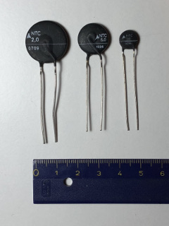
Three different sizes of NTC inrush current limiters.
The cold resistance is directly marked on the body.
(click to enlarge).
Designing an inrush limiter is a topic on its own and requires suitable NTCs which are rated for the desired current and power dissipation. I've seen NTCs rated up to 20 A with cold resistances roughly ranging from 1 to 100 Ω. Cold resistance is simply R25, but in this application is more often called cold resistance; when measuring temperatures, the term nominal resistance or R25 is often preferred, but it's the same thing. The basic idea is that this cold resistance added to the one of the load at startup should limit the current to a safe value, while the maximum current rating of the NTC should exceed the maximum current of the load. For this application the β is less important and other parameters should be considered, like the maximum current, the maximum voltage or the maximum thermal dissipation, which don't play a significant role in a thermometer application. Thermal considerations must also be taken into account, but designing an inrush limiter is beyond the scope of this page.
NTC are cheap and easy to find temperature sensors, but are nonlinear and require some math, some tricks and some compromises to determine the actual temperature. Some of those aspects have been described in this page. However, it's not intended to replace a good electronics book nor detailed application notes of NTC manufacturers; it's more to share some thoughts and give a rough idea on how I do it. The calculators available in this page may help in determining which NTC will fit your application or the main parameters of the ones you have available. The equations of a fairly accurate mathematical model are also explained, so that you can easily implement them in a spreadsheet and have an even better calculator for your application. NTCs can also be used as inrush current limiters, but this is a completely different topic that is beyond the scope of this page.
| [1] | Panasonic. The NTC thermistor. Application note, 2004. |
| Home | Electronics | Page hits: 251391 | Created: 08.2009 | Last update: 02.2018 |